Product Details
Description
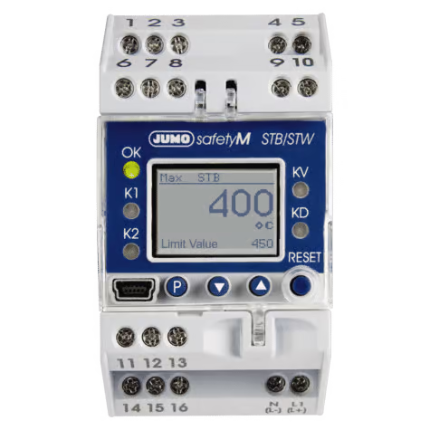
The safety temperature limiter (STB) and safety temperature monitor (STW) enable early and reliable detection of risks which could potentially result in personal injuries, environmental damage, or destruction of the production plant and production materials.
Its primary task is to reliably monitor thermal processes and to switch plants to a safe operating status in the event of malfunctions.
The measured value at the analog input can be recorded by various probes or standard signals. Limit value exceedance is indicated by the installed LED K1 and K2 (red) for each channel and the integrated alarm relay output switches the plant to safe operating status (alarm range).
Safety temperature monitor (STW)
Protective temperature monitor with automatic reset for heat-generating plants. An automatic reset occurs upon activation after the probe temperature has risen or fallen above/below the set limit value by the amount of the switching differential.
(Modes of operation 2B, 2K, and 2P)
Safety temperature limiter (STB)
Protective temperature limiter for heat-generating plants that can only be reset manually or with a tool.
(Functions 2B, 2J, 2 V, 2K, 2P and adjustable with special tool)
STB/STW Features
- Can be configured as safety temperature limiter (STB) or safety temperature monitor (STW)
- 1oo2D architecture
- Approvals for DIN EN 14597, SIL, PL (Performance Level), UL
- Two relay outputs can be used as pre-alarm or limit value alarm
- Pre-alarm absolute or adjustable as a margin from the limit value
- LCD display with background lighting and plain text display
- Setup program for configuration and archiving via USB interface
- Wide voltage supply range from 110 to 240 V +10 %/-15 % or ACDC 20 to 30 V
- Internal and external unlocking possible
Technical Specs
Analog inputs
RTD temperature probe
| Designation |
Measuring range |
Accuracy
2/3-wire circuit1 |
Ambient temperature error |
| Pt100 DIN IEC 60751:2008 |
-200 to +850 °C |
0.5 %/0.1 % |
50 ppm/K |
| Pt1000 DIN IEC 60751:2008 |
-200 to +850 °C |
0.5 %/0.1 % |
50 ppm/K |
| Connection type |
Maximum lead wire resistance 2-wire circuit 15 Ω, 3-wire circuit 30 Ω |
| Sampling rate |
210 ms |
| Error tolerance time |
≤ 5 s: time taken into account for all diagnostic tests |
| Input filter |
Digital filter, 2nd order; filter constant can be set from 0 to 100 s |
| Special features |
Single probe Pt100 2-wire, display can also be programmed in °F |
Thermocouples
| Designation |
Measuring range |
Accuracy1 |
Ambient temperature
influence |
| Fe-CuNi “L” DIN 43710: 1985-12 |
-200 to +900 °C |
0.4 % |
100 ppm/K |
| Fe-CuNi “J” DIN EN 60584-1:1996-10 |
-200 to +1200 °C |
0.4 % |
100 ppm/K |
| Cu-CuNi “U” DIN 43710:1985-12 |
-200 to +600 °C |
0.4 % |
100 ppm/K |
| Cu-CuNi “T” DIN EN 60584-1:1996-10 |
-200 to +400 °C |
0.4 % |
100 ppm/K |
| NiCr-Ni “K” DIN EN 60584-1:1996-10 |
-200 to +1372 °C |
0.4 % |
100 ppm/K |
| Pt10Rh-Pt “S” DIN EN 60584-1:1996-10 |
-50 to +1768 °C |
0.4 % |
100 ppm/K |
| Pt13Rh-Pt “R” DIN EN 60584-1:1996-10 |
-50 to +1768 °C |
0.4 % |
100 ppm/K |
| Pt30Rh-Pt6Rh “B” DIN EN 60584-1:1996-10 |
0 to 1820 °C |
0.4 %2 |
100 ppm/K |
| NiCrSi-NiSi „N“ DIN EN 60584-1:1996-10 |
-100 to +1300 °C |
0.4 %2 |
100 ppm/K |
| W3Re-W25Re “D”ASTM E1751M-09 (bis 2315 °C): 2009 |
0 to 2495 °C |
0.4% |
100 ppm/K |
| W5Re-W26Re „C“ ASTM E230M-11: 2011 |
0 to 2315 °C |
0,4% |
100 ppm/K |
| Cold junction |
Pt100 internal |
| Cold junction accuracy |
±1 K |
| Sampling rate |
210 ms |
| Error tolerance time |
≤ 5 s: time taken into account for all diagnostic tests |
| Input filter |
Digital filter, 2nd order; filter constant can be set from 0 to 100 s |
1. The accuracy refers to the maximum extent of the measuring range.
2. The accuracy is garanteed above 300° C
Direct current
| Measuring range |
Accuracy |
Ambient temperature influence |
| 4 to 20mA, voltage drop < 2 V |
0.2 % |
150 ppm/K |
| Scaling |
Can be freely programmed within the limits |
| Sampling rate |
210 ms |
| Error tolerance time |
≤ 5 s: time taken into account for all diagnostic tests |
| Input filter |
Digital filter, 2nd order; filter constant can be set from 0 to 100 s |
| Special features |
Single probe 4 to 20 mA |
Analog output
|
Signal type |
Accuracy |
Residual ripple |
Load influence |
Temperature influence |
Load resistance |
| Current |
4 to 20 mA |
≤ 0.5 % |
± 0.5 % at 300 Ω |
± 0.05 mA/100Ω |
150 ppm/K |
≤ 500 Ω |
| 0 to 20 mA |
| Voltage |
2 to 10 V |
≤ 0.5 % |
± 0.5 % |
± 15 mV |
150 ppm/K |
÷ 500 Ω |
| 0 to 10 V |
Binary input
| Connection |
Function |
| 1 floating contact |
Unlocking, key inhibit, level inhibit can be configured |
Relay outputs
| Relay output KV |
Relay (changeover contact) without contact protection
30000 switching operations at a switching capacity of 250 V, 3 A, 50 Hz (resistive load)
or up to DC 30 V, 3 A. Minimum current DC 12 V, 100 mA. |
| Relay output alarm |
Relay (changeover contact)
Contact protection circuit: fuse cut-out 3.15 AT, installed in the pole contact arm
30000 switching actions at a switching capacity of 230 V, 3 A, 50 Hz (resistive load)
or up to DC 30 V, 3 A. Minimum current DC 12 V, 100 mA. |
Measuring circuit monitoring
|
RTD temperature probe in 3-wire circuit and double thermocouples |
Thermocouples |
|
Current 4 to 20 mA |
| Overrange and underrange |
Is detected
LED K1, K2, KD, and KV are lit;
“>>>>“ flashes in the display for overrange, “<<<<“ for underrange. |
| Probe/cable break |
Is detected
LED K1, K2, KD, and KV are lit
“>>>>“ flashes in the display; relay output alarm is inactive |
LED K1, K2, KD, and KV are lit;
“>>>>“ flashes in the display; relay output alarm is inactive |
| Probe short circuit |
Is detected
LED K1, K2, KD, and KV are lit
“<<<<“ flashes in the display; relay output alarm is inactive |
Is detected by difference monitoring of the analog inputs |
LED K1, K2, KD, and KV are lit;
“<<<<“ flashes in the display; relay output alarm is inactive |
Voltage supply
| Voltage supply |
AC/DC 20 to 30V, 48 to 63 Hz |
AC 110 to 240V +10% /-15%, 48 to 63 Hz |
| Power consumption, Power loss |
max. 12 W |
max. 12 W |
Power consumption, Power loss
for the following mode:
Analog output 10mA; background lighting Display off; Relay output “Alarm” on;
Relay output pre-alarm off; Sensor: 2xPt100 |
5W |
5W |
Test voltages according to EN 60730, part 1
| Input and output against voltage supply |
|
| – At voltage supply AC 110 to 240 V +10 % / -15 % |
3.7 kV/50 Hz |
| – At voltage supply AC/DC 20 to 30 V, 48 to 63 Hz |
3.7 kV/50 Hz |
Electrical safety
|
Clearances / creepage distances |
| Mains voltage to electronic components and probes |
≥ 6 mm / ≥ 8 mm |
| Mains voltage to the relay |
≥ 6 mm / ≥ 8 mm |
| Relay to electronic components and probes |
≥ 6 mm / ≥ 8 mm |
| Electrical safety |
According to DIN EN 14597 (DIN EN 60730-2-9)
Overvoltage category III, pollution degree 2 |
| Protection rating I |
With internal separation to SELV electrical circuits |
Environmental influences
| Ambient temperature range |
0 to +55 °C |
| Storage temperature range |
-30 to +70 °C |
| Temperature influence |
≤ ± 0.005 % / K dev. from 23 ×C1 for RTD temperature probe |
|
≤ ± 0.01 % / K dev. from 23 ×C1 for thermocouple, current |
| Terminal temperature Range |
If the temperature range of -10 °C to +80 °C is exceeded or undercut, the device shows the error
message “Terminal temperature Range“.
The output changes to a safe state (quiescent current principle).
The message can only be acknowledged, if the temperature is back again in the valid range. |
| Resistance to climatic conditions |
85 % rel. humidity without condensation
(3K3 with extended temperature range according to DIN EN 60721-3-3) |
| EMC |
According to DIN EN 14597 and standards from the standard series DIN EN 61326 |
| Interference emission |
Class B |
| Interference immunity |
Evaluation criteria FS according to DIN EN 14597, regulation and control devices (RS) |
1. All specifications refer to the measuring range end value
Case
| Material |
Polycarbonate |
| Flammability class |
UL 94 V0 |
| Electrical connection |
On the front via screw terminals up to 2.5 mm2 |
| Installation |
On 35 mm DIN rail acc. to EN 60715 |
| Installation position |
vertical |
| Weight |
Approx. 230 g |
| Protection type |
IP 20 acc. to EN 60529 |
Approvals/approval marks
| Approval marks |
Testing agency |
Certificates/certification numbers |
Inspection basis |
Valid for |
| DIN |
DIN CERTCO |
STB/STW1223 |
DIN EN 14597 |
All device versions: |
| SIL2, SIL3 |
TÜV Nord (German Technical Inspection Agency) |
SEBS-A.102606/16-2 V1.0 |
DIN EN 61508 |
Devices with extra code 058 |
| PL e |
DIN EN ISO 13849-1 |
| c UL us |
Underwriters Laboratories |
E325456-20120611 |
UL 60730-2-9 submitted |
All device versions: |
| DNV·GL |
DNV·GL |
TAA000017J |
|
Devices with extra code 062 |
Pressure Equipment
Directive |
TÜV Süd (German Technical Inspection Agency) |
07 202 1045 Z 0031/14/D0046 |
Pressure Equipment Directive 97/23/EG |
All device versions: |