Product Details
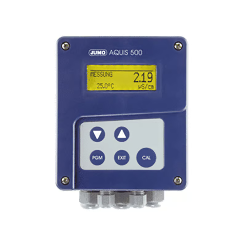
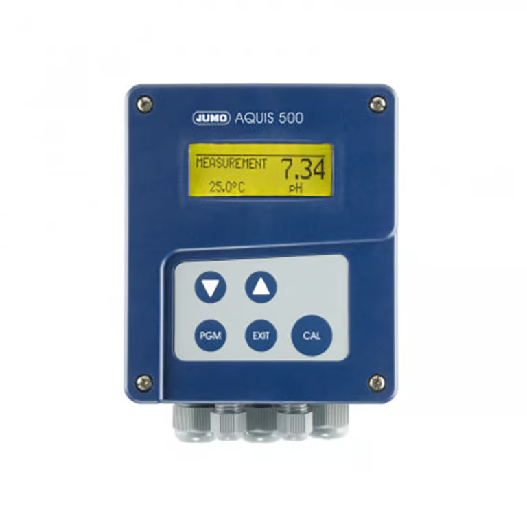
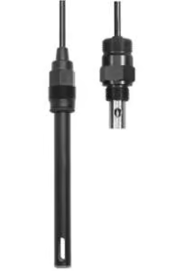
The AQUIS 500 CR is used for the conductive measurement/control of electrolytic conductivity, resistivity or the TDS value. In addition, the instrument also offers the possibility of showing the measured conductivity according to a customer-specific table. Conductive two-electrode cells as well as four-electrode cells can be connected to the instrument.
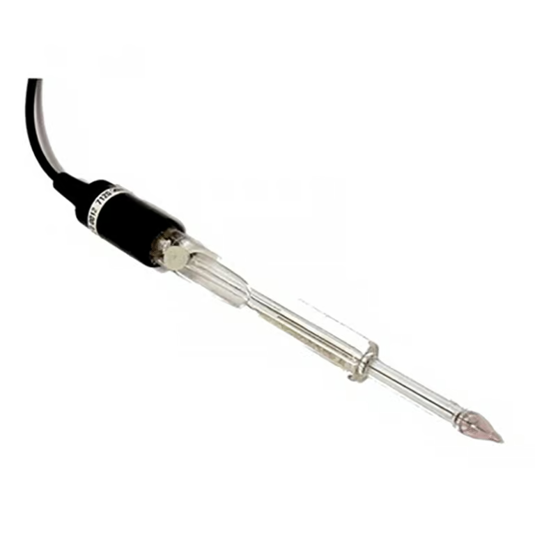
Temperature serves as the second input variable, measured by a Pt100/1000 probe. Depending on the measured variable, it is therefore possible to implement specific, automatic temperature compensation.
The instrument is operated using keys and a large LC graphics display on which the measurements are clearly legible. The plain-text presentation of the parameters makes it easier for the user to configure the instrument, and also helps in programming it correctly.
Thanks to its modular design, the instrument can be perfectly matched to the particular application requirement.
AQUIS 500 CR Features
- Multi-lingual plain text operation
- Graphical display with background lighting
- Surface mounting housing, protection class IP67
- Easy to install pluggable terminal strips
- Electrode monitoring
Typical Application
- Water and wastewater engineering
- Service/process water and wastewater management
- Drinking water and well/surface water management
- Pure and high-purity water as well as pharmaceutical water management (e.g. as per USP, Ph.Eur, WFI)
- Water quality measurements
- TDS measurements (ppm or mg/l)
Technical Specs
Inputs
| Principal input |
Indication range |
Accuracy |
Temperature error |
| µS/cm |
0.000 v 9.999
00.00 to 99.99
000.0 to 999.9
0000 to 9999 |
≤ 0.6 % of range + 0.3 µS x cell constant (K) |
0.2 %/10°C |
| mS/cm |
0.000 to 9.999
00.00 to 99.99
000.0 to 999.9
0000 to 9999 |
≤ 0.6 % of range + 0.3 µS x cell constant (K) |
0.2 %/10°C |
| kΩ x cm |
0.000 to 9.999
00.00 to 99.99
000.0 to 999.9
0000 to 9999 |
≤ 0.6 % of range + 0.3 µS x cell constant (K) |
0.2 %/10°C |
| MΩ x cm |
0.000 to 9.999
00.00 to 99.99
000.0 to 999.9
0000 to 9999 |
≤ 0.6 % of range + 0.3 µS x cell constant (K) |
0.2 %/10°C |
|
|
|
|
| Secondary input |
Measuring range |
Accuracy |
Temperature error |
Temperature Pt100
(automatic detection) |
-50°C~250°Ca |
±0,5 K (up to 100°C)
±0,8 K (as of 100°C) |
0.05 %/10°C |
Temperature Pt1000
(automatic detection) |
±0,5 K (up to 100°C)
±1,0 K (as of 100°C) |
| Temperature NTC/PTC |
max. 4 kOhm
Input via table
with 20 value pairs
through setup program |
≤ 0.3 %b |
0.05 %/10°C |
a Switchable to °F
b Depending on interpolation points
Temperature compensation
| Type of compensation |
Rangea |
| Linear 0 to 8 %/°C |
-10°C~160°C |
| ASTM D1125 – 95 (high-purity water) |
0°C~100°C |
| Natural water (ISO 7888) |
0°C~36°C |
| Reference temperature |
| adjustable from 15°C to 30°C; preset to 25°C (standard) |
a Please note operating temperature range of sensor
Measuring circuit monitoring
| Inputs |
Over/underrange |
Short-circuit |
Cable break |
| Conductivity |
yes |
depending on range |
depending on range |
| Temperature |
yes |
yes |
yes |
2-electrode systems
| Cell constant [1/cm] |
Setting range of relative cell constant |
Resulting usable range [1/cm] |
| 0.01 |
20 to 500 % |
0.002 to 0.05 |
| 0.1 |
0.02 to 0.5 |
| 1.0 |
0.2 to 5 |
| 3.0 |
0.6 to 15 |
| 10.0 |
2.0 to 50 |
4-electrode systems
| Cell constant [1/cm] |
Setting range of relative cell constant |
Resulting usable range [1/cm] |
| 0.5 |
20 to 150 % |
0.1 to 0.75 |
| 1.0 |
0.2 to 1.5 |
Binary input
| Activation |
Through floating contact |
| Function |
Key inhibit
HOLD
Alarm suppression |
Controller
| Controller type |
Limit comparators, limit controller, pulse width controller, pulse frequency controller, modulating controller, continuous controller |
| Controller action |
P/PI/PD/PID |
| A/D converter |
dynamic resolution up to 14-bit |
| Sampling time |
500 msec |
Analog outputs (one or two)
| Output mode |
Signal range |
Accuracy |
Temperature error |
Permissible load resistance |
| Current signal |
0/4 to 20 mA |
≤ 0.25 % |
0.08 %/10 °C |
≤ 500 Ω |
| Voltage signal |
0 to 10 V |
≤ 0.25 % |
0.08 %/10 °C |
≥ 500 Ω |
The analog outputs respond in accordance with the recommendation as per NAMUR NE43
They are electrically isolated, AC 30 V/DC 50 V |
Switching outputs (two changeover (SPDT) max.)
| Rated load |
3 A/250 VAC (resistive load) |
| Contact life |
>2×10⁵ operations at rated load |
Setup interface
Interface for configuring the device through the optionally available setup program (for device configuration only)
Electrical data
| Supply voltage |
AC 110 to 240 V; -15/+10 %; 48 to 63 Hz
AC/DC 20 to 30 V; 48 to 63 Hz
DC 12 to 24 V; +/-15 % (permissible only for connection to SELV/PELV circuits) |
| Power consumption |
approx. 14 VA |
| Electrical safety |
EN 61 010, Part 1
overvoltage category IIIa, pollution degree 2 |
| Data backup |
EEPROM |
| Electrical connection |
pluggable screw terminals
conductor cross-section up to 2.5 mm2 (supply, relay outputs, sensor inputs)
conductor cross-section up to 1.5 mm2 (analog outputs) |
a Not valid with protective extra-low voltage (PELV) of power supply variant DC 12 to 24 V
Display
| Graphics LC display |
120 x 32 pixels |
| Background lighting |
programmable:
– off
– on for 60 seconds during operation |
Housing
| Material |
ABS |
| Cable entry |
cable glands, 3xM16 and 2xM12 max |
| Special feature |
venting device to prevent condensation |
Ambient temperature range
(the specified accuracy is adhered
to within this range) |
-10°C~50°C |
Operating temperature range
(device is operational) |
-15°C~65°C |
| Storage temperature range |
-30°C~70°C |
| Climatic conditions |
rel. humidity ≤ 90 % annual mean, no condensation
(following EN 60721 3-3 3K3) |
Enclosure protection
as per EN 60529 |
in surface mountable housing: IP67
for panel mounting: IP65 front, IP20 rear |
| Vibration strength |
as per EN 60068-2-6 |
| Weight |
surface mountable housing: approx. 900 g
for panel mounting: approx. 480 g |
| Dimensions |
see dimensioned drawings on page 10 of the attached data sheet |
Standard accessories
Cable glands
Internal mounting material
Operating Instructions
Approvals/approval marks
| Mark of confirmity |
Testing laboratory |
Certifikates/certification numbers |
Test basis |
valid for |
| c UL us |
Underwriters Laboratories |
E 201387 |
UL 61010-1 |
all versions |